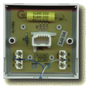
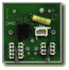
 Wiring of a normal telephone extension on a normal telephone circuit requires
a Secondary socket connected back to the master
socket and all of the other secondary sockets in parallel (all connected
together). This uses two pairs to connect from one socket to the next.
Wiring of telephone extension from a PABX normally requires a master socket for each extension connected back to the PABX or distribution box. This uses one pair for each extension.
Wiring ISDN extension sockets requires a Cat5/ISDN RJ45 socket. Each socket is connected to the previous in a daisy chain arrangement back to the master socket network termination point or PABX, or distribution box.
A distribution box can be used to help organize the wiring when wiring a home/office with a PABX, as each extension has to be wired back to one point. These can also be used for network 10base-T cabling.
Normal telephone cable is used for ISDN or telephone sockets, and can be used for networking. However, for network cabling, Cat5 is recommended.
Whilst screw terminals can be used on sockets, it is often simpler and
more reliable to use IDC (Insulation Displacement Connector)
instead. This requires a tool which pushes the cable in to the connectors.

The pair of wires is connected to pins 2 and 5 of the master socket. Extensions can then be run using pairs on 2/5 and on 3/4.
The actual connections are normally coloured as follows :-
| Colour | Usage |
 |
||
|---|---|---|---|---|
| 1 | Green/White | Spare | ||
| 2 | Blue/White | Telephone | ||
| 3 | Orange/White | Ring | ||
| 4 | White/Orange | Earth | ||
| 5 | White/Blue | Telephone | ||
| 6 | White/Green | Spare | ||

Connect all of the secondary sockets together, connecting pins 2 and 5 as a one pair and 3 and 4 as another, and always connecting all of the wires to the same pins on all of the sockets and connecting all of the wires back to the master socket.
| Colour | Cat5
10baseT/Tel |
ISDN |
 |
||
|---|---|---|---|---|---|
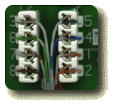
| 1 | White/Orange | Tx+/- | Power 3
optional |
||
| 2 | Orange/White | ||||
| 3 | White/Green | Rx+ | TE->NT + | ||
| 4 | Blue/White | Telephone
A/B |
NT->TE + | ||
| 5 | White/Blue | NT->TE - | |||
| 6 | Green/White | Rx- | TE->NT - | ||
| 7 | White/Brown | Power 2
optional |
|||
| 8 | Brown/White | ||||
There are two switches on the NT (box connecting to the BT line), one is for IN/OUT indicating that the terminating resistors in the box are in or out. The other is marked L/S indicating long or short lines.
You can wire ISDN using only two pairs (4/5 and 3/6) as the additional pairs are optional power lines. The optional power lines are not used by most ISDN phones as there is also power provided on 3/4/5/6. Note that a standard BT line does not have enough power to run a normal ISDN phone, but this is relevant where wiring extensions from a PABX with internal ISDN lines.
We supply RJ45/Cat5 sockets as single, double, or dual with a telephone
socket on the same plate.

See this page for Cat5 plug wiring
However... If you want, you can run normal telephone cable 4 pair from your distribution box to each point in you home/office and fit a dual Cat5/RJ45 and master socket (picture at top of page). This allows for network cabling, ISDN extensions and telephone.
To make 4 pairs work for all three tasks, you need to connect one pair for telephone (2/5 on the master socket), and 3 pairs to the RJ45 socket.
10baseT only needs 1/2, and 3/6, whilst ISDN only needs 3/6 and 4/5, so connecting 1/2, 3/6, and 4/5, you can use the socket for either purpose. (Remember however that you should use 100ohm termination resistors at the end of an internal ISDN extension, which might upset 10base-T).
This solution is obviously not a future proof as full Cat5 structured
cabling, but for a home office, it is a cheap solution.

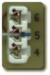
The contacts do not work loose like screw terminals, and do not risk shorting by having too much insulation stripped away. You can normally push four wires in to each IDC point if necessary.
 You can use a simple plastic IDC tool to push the wires in to the contacts,
or you can use a professional IDC tool with a cutter that neatly trims
excess wire, steal one from a BT engineer if you can.
.
Place the wire across the contact, and push down with the tool firmly.
With the professional tool, it will click and cut off the excess when you
have pushed the wire home with enough pressure. You do not need to strip
the insulation off each wire. You should only use a proper IDC tool, and
never a screwdriver Gary.
 The professional tool also has a hook to allow you to easily pull out any
wires you need to (useful when using a distribution box).
It also has a clip which can be fitted to the collar of the tool to stop
the cutting action (useful when the wire must continue to another contact
rather than being cut off).
 A
distribution box is invaluable for organizing wiring, and allowing changes
at a later stage.
The box itself has plastic panels in the sides that can be removed allowing several boxes side by side to make a larger distribution box. There are also break outs of various size for cables to enter the box from the sides, and holes in the back to allow cables from the rear.
The connector strips each accommodate 10 pairs, and the box will take a total of 5 strips. Each pair is numbered 1-9/0 so that the pairs can be identified easily. The strips have slots and pegs at the back to allow cabling to be neatly connected and cable tied to the back of the strip.
Each strip has two sides which are connected together - although a test
jack can be inserted to separate the connection between each side of
the strip and could be used for testing.
A simple way to wire these boxes is to fit all of the permanent
wiring to one side of the strips, and then run wiring from the other side
to patch to other strips. e.g. wiring in the home/office goes to
one size of one strip, and wiring to the PABX goes to one side of the other
strip, and then wires are connected between the two. This arrangement allows
the connections to be changed easily without having to move the fixed
wiring which has been neatly cut to length and fitted to strips.

The colouring is normally done by having one wire in the pair white with coloured bands, and the other in the pair coloured with white bands.