+3.3v 1 11 +3.3v and +3.3v Sense +3.3v 2 12 -12v GND 3 13 GND +5v 4 14 PWR_ON GND 5 15 GND +5v 6 16 GND GND 7 17 GND PW_OK 8 18 -5v +5v standby 9 19 +5v +12v 10 20 +5v
Last modified: Mon 25 Jan 2010
This is a collection of pinouts that I've gathered over the years and umpteen hours of buzzing out cables.
. RS-232 connection table
   Source	Destination	          Signal      Colour
   ------	-----------		  ------      -----
   TXD		RXD			   TXD        Orange
   RXD		TXD			   RXD	      Black
   RTS		CTS 			   RTS	      Red
   CTS		RTS			   CTS	      Green
   GND		GND			   GND	      Brown
   DCD	        DTR			   DCD	      Blue
   DTR		DCD			   DTR	      White
          -------------------
          \  5  4  3  2  1  /
           \   9  8  7  6  /
            ---------------

        Pin | Name | Description
        --------------------------------
Orange   2  | TD   | Transmit Data
Black    3  | RD   | Receive Data
Red      4  | RTS  | Request To Send
Green    5  | CTS  | Clear To Send
Brown    7  | SG   | Signal Ground
White    8  | DCD  | Data Carrier Detect
Blue     9  | DTR  | Data Terminal Ready
          -------------------
          \  1  2  3  4  5  /
           \   6  7  8  9  /
            ---------------

     Pin | Name | Description
     --------------------------------
Blue  1  | DCD  | Data Carrier Detect
Black 2  | RD   | Receive Data
Orange3  | TD   | Transmit Data
White 4  | DTR  | Data Terminal Ready
Brown 5  | GND  | Signal Ground
Red   7  | RTS  | Request To Send
Green 8  | CTS  | Clear To Send
                   ---------
                  / 8  7  6 \
                 (  5  4  3  )
                  \  2   1  /
                   ---------

    Pin   | Name    | Description
   -----------------------------------------
     1    | DTR     | Data Terminal Ready
     2    | CTS     | Clear To Send
     3    | TD      | Transmit Data
     4    | SG      | Signal Ground
     5    | RD      | Receive Data
     6    | RTS     | Request To Send
     7    | DCD     | Data Carrier Detect
     8    | SG      | Signal Ground
Since there is no such thing as a RJ-MiniDIN-8 adaptor,
an SGI P/N X5-9to8 pigtail is used to give a female DB9
on systems with Mini-DIN-8 connectors.
                         ------
                        / 5 3  \
                       | ---  1 |
                       | ---  2 |
                        \ 6 4  /
                         ------

                     Pin Assignments
                   ___________________
                   Pin_|_Description__
                    1  | Data
                    2  | Reserved
                    3  | Signal Ground
                    4  | Power +5V
                    5  | Clock
                    6  | Reserved
                         ------
                        / 5 3  \
                       | ---  1 |
                       | ---  2 |
                        \ 6 4  /
                         ------

                     Pin Assignments
                   ___________________
                   Pin_|_Description__
                    1  | KRCD	Keyboard Receive
                    2  | MRCD	Mouse Receive
                    3  | GND	Ground
                    4  | Power  +8V
                    5  | KTXD	Keyboard Transmit
                    6  | Power	-8v
	DB15 Male	DIN 6		Signal/Signal
	---------	-----		-------------
	2		3		Gnd/Gnd
	4		1		K_TXD/K_RXD
	5		5		K_RXD/K_TXD
	9		4		+12/+8
	10		2		M_TXD/M_RXD
	15		6		???/???
	DB15 Male	DB-9		Signal/Signal
	---------	-----		-------------
	1		-		Ground
	2		6		Ground
	3		9		Ground
	4		2		K_TXD/K_RXD
	5		8		K_RXD/K_TXD
	7		7		+12
	8		-		+12
	9		-		+12
	10		5		M_TXD/M_RXD
	15		4		-12
This is a "Y" cable; two mini-din6 connectors are wired to one RJ45 plug. A pair of adaptors is needed, one mini-din6 female set, and one mini-din6 male set. Custom made by Anixter 408/435-1212
  Mini-Din6 #1		RJ45 plug
(male or female)
  ------------		---------
      5			1
      4			2
      3			3
      1			4
   Mini-Din6 #2
  -------------
      5			5
      4			6
      3			7
      1			8
o2 (female)    Dial Box (female)
---------     ----------
    1 (DCD) ---------->8 (DCD)
    2 (RD)  ---------->3  (RD)
    3 (TD)  ---------->2  (TD)
    5 (SG)  ---------->7 (GND)
    7 (RTS) ---------->4 (RTS)
    8 (CTS) ---------->5 (CTS)
idc 8x2		db9
2  (td)		3	rd
10 (rd)		2	td
13 (gd)		7	gnd
   PBX #      Signal
   -----      ------
   1           DTR
   2           GND
   3           N/C
   26          TXD
   27          RXD
   28          CTS

      ------------------------
     /26 27 28 29 30  .... 50 \
    / 1  2  3  4  5   .... 25  \=======
    ----------------------------=======

Groupings of colours, suitable for punching down to an RJ45 8pin
crossconnect panel:

1.             2.        3.       4.
   W / Bl    W / Br    R / O     R / Gy
  Bl / W    Br / W     O / R    Gy / R
   ----     ------     ----     ------
   G / W    Bl / R    Br / R     O / K
   W / O     W / Gy    R / Gr    K / Bl
   O / W    Gy / W    Gr / R    Bl / K
   W / G     R / Bl    R / Br    K / O
   -----    ------     -----    ------

5.             6.        7.       8.
   K / Gr    Y / Bl    Y / Br    P / O
  Gr / K    Bl / Y    Br / Y     O / P
   ----     ------     ----     ------
  Gy / K    Gr / Y    Bl / P    Br / P
   K / Br    Y / O     Y / Gy    P / Gr
  Br / K     O / Y    Gy / Y    Gr / P
   K / Gy    Y / Gr    P / Bl    P / Br
   -----    ------     -----    ------
Modular adapters (Ortronics' P/N OR-8120M25-8/6) are used to adapt the
50pin PBX connector to eight (8) six pin RJ45 plugs.
Each 6 pin RJ45 plug has the following pinout: RJ45 PBX # Signal ----- ----- ------ 1 28 CTS 2 27 RXD 3 1 DTR 4 26 TXD 5 2 GND 6 3 N/CConnecting a 6 conductor straight through RJ45 data cable from this plug to a standard RJ45 to DB-style connector (see above) yields the following colour / signal table. THIS IS THE IMPORTANT TABLE!
   RJ45 #	DB Colour	Signal
   ------       -----           ------
   1		Blue		USED FOR 8 PIN CONNECTIONS ONLY
   2		Orange		CTS
   3		Black		RXD
   4		Red		DTR
   5		Green		TXD
   6		Yellow		GND
   7		Brown		N/C
   8	        White		USED FOR 8 PIN CONNECTION ONLY
The console connection for an Annex 2 is on port 1. Use one of the below connectors to hook it up to the desired gadget.
   DB Pin       RJ colour
   --------     -------
   2	TXD	Black
   3	RXD	Green
   5	CTS	Red
   7	SG	Yellow
   9	DTR	Brown
UNKNOWN
	Annex RJ45-6pin:  Standard Data cable crimp (see above)

	Cisco RJ45-8pin:
             3  G
	     5  Y
	     6  K
     	    clip all other wires
     DB Pin	RJ Colour
     ------	--------
	2	Green
	3	Black
	7	Yellow
     (standard pinout)
	RJ End 1	RJ End 2
	--------	--------
	1  Blue		1 White
	2  Yellow	2 Green
        3  Green	3 Black
	4  Red		4 Red
        5  Black	5 Yellow
        6  White	6 Blue
     DB Pin	RJ Colour
     ------	--------
	2	Black
	3	Green
	7	Yellow
     DB Pin	RJ Colour
     ------	--------
	2	Black
	3	Green
	7	Yellow
	4,5,8	tie together
     DB Pin	RJ Colour
     ------	--------
	2	Black
	3	Green
	5	Yellow
	7	Brown
	8	Red
     DB Pin	RJ Colour
     ------	--------
	2	Green
	3	Black
	5	Yellow
	(rj45 jack metal-side up)

	rj45	colour
	2	w/r	(gnd)
	3	w/k	(rd)
	5	k/w	(td)
   PBX #       Signal
   -----       ------
   1           DCD
   2           GND
   3           DSR
   4	       RTS
   26          RXD
   27          TXD
   28          DTR
   29          CTS

      ------------------------
     /26 27 28 29 30  .... 50 \
    / 1  2  3  4  5   .... 25  \=======
    ----------------------------=======
Modular adapters (Ortronics' P/N OR-???????????) are used to adapt the
50pin PBX connector to six (6) eight pin RJ45 plugs.
Each 8 pin RJ45 plug has the following pinout: RJ45 DB Colour PBX # Signal ----- -------- ----- ------ 1 Blue 27 TXD 2 Orange 2 GND 3 Black 28 DTR 4 Red 1 DCD 5 Green 26 RXD 6 Yellow 3 DSR 7 Brown 29 CTS 8 White 4 RTS
The console connection on an Annex 3 is on a seperate RJ45 plug on the back of the system. Use a standard RJ45-DB25 adaptor with the following pinout to connect it to a terminal:
   RJ45 #	DB Colour	Signal
   ------       -----           ------
     2		Green
     3		Black
     4		White
     5		Blue
     6		connect to pin 9
     7		Orange
     8		Yellow
     20		Red
   DB Pin       RJ colour
   --------     -------
   1		White
   2		Green
   3		Blue
   6		Brown
   7		Orange
   DB Pin       RJ colour
   --------     -------
   2		Blue
   3		Green
   5		Orange
     (standard pinout)
	RJ End 1	RJ End 2
	--------	--------
	1 Blue		1 Black
	2 Orange	2 Red
	3 Black		3 Blue
	4 Red		4 Orange
	5 Green		5 Yellow
	6 Yellow	6 Green
	7 Brown		7 Brown
	8 White		8 White
	DB Pin		RJ Colour
	--------	--------
	2		Blue
	3		Green
	7		Orange
   RJ Pin	Signal     DB/RJ Colour
   ------	------     -----------
    1		RTS	   Blue
    2		DTR        Orange
    3		TXD	   Black
    4		DCD	   Red
    5		RXD	   Green
    6		GND	   Yellow
    7		DSR	   Brown
    8		CTS	   White
Note that some ports on MicroAnnexen may not support full modem control.
These ports are missing RTS, DCD, and DSR.
   DB Pin   DB Signal     RJ colour
   ------   ---------     -------
   2	      TD          Green
   3	      RD          Black
   7	      GND         Yellow
Short 4,5,8 together if you need to spoof flow control. Challenge System Controller Ports need this.
   DB Pin       RJ colour
   --------     -------
   2		Black
   3		Green
   7		Yellow
   4,5,8	tie together
   DB Pin       RJ colour
   --------     -------
   2		Green
   3		Black
   7		Yellow
   DB Pin       RJ colour
   --------     -------
   2		Black
   3		Green
   7		Yellow
    Cisco RJ45-8pin: Standard Data cable crimp (see above)

    Annex RJ45-8pin:

     3    Yellow  or Gr/Wh
     5    Black   or Wh/Gr
     6    Red     or Bl/Wh

1-2,4,7-8 can be connected as usual with no harm.

The ends are sensitive; you *must* plug the Cisco end into the Cisco,
and the Annex end into the Annex.
SGI "Etherlite" terminal servers are remarketed products from Central Data Systems. They are 8, 16, or 32 port ethernet based serial ports, connected "directly" to the SGI host system via a kernel driver and some system daemons -- they give normal looking devices as /dev/tty[mdf][\d][\d+]. You need the 'el_serial' inst package installed to use these servers. Good additional information on the drivers is at
         .---.                +--------------------------+
        _|   |_               | pin | signal | direction |
       |       |              |--------------------------|
 .-----~       ~-----.        |  1  |  RTS   |    out    |
 |                   |        |  2  |  DSR   |    in     |
 |                   |        |  3  |  DCD   |    in     |
 |                   |        |  4  |  RxD   |    in     |
 |                   |        |  5  |  TxD   |    out    |
 |                   |        |  6  |  GND   |    n/a    |
 |                   |        |  7  |  DTR   |    out    |
 +__|_|_|_|_|_|_|_|__+        |  8  |  CTS   |    in     |
    8 7 6 5 4 3 2 1           +--------------------------+

RJ45 shown above 		DB9 on Origin:
1  |  RTS		     	Blue  	7
2  |  DSR 			Orange	N/A
3  |  DCD			Black 	1
4  |  RxD 			Red   	3
5  |  TxD			Green 	2
6  |  GND			Yellow	5
7  |  DTR 			Brown	4
8  |  CTS 			White 	8

RJ45 shown above		DB9 on Challenge
1  |  RTS 			Blue 	4
2  |  DSR  			Orange	N/A
3  |  DCD			Black	8
4  |  RxD 			Red	2
5  |  TxD			Green	3
6  |  GND 			Yellow	7
7  |  DTR			Brown	9
8  |  CTS			White	5
Using straight-through 8-pin RJ45 cables and the various pinouts listed in this section, it is possible to mix-and-match the connectors to what is needed. Connect two "modem" adaptors (one DB25 Male for the modem, one DB9 Male for the SGI) for a modem cable, or exchange one "modem" adaptor for a "null" adaptor to create a null modem cable to connect a terminal to an SGI, or two SGI systems back-to-back. Since there is no such thing as a RJ-MiniDIN-8 adaptor, an SGI P/N X5-9to8 pigtail is used to give a female DB9 on systems with Mini-DIN-8 connectors.
     Male                      Female   Male
   DB25 Pin	RJ Colour       DB9 Pin  DB9 Pin		RJ Colour
   --------	--------       -------  -------         --------
        2       Orange         1  Blue    1    N/C      Yellow
        3       Black          2  Black   2    TD       Orange
        4       Red            3  Orange  3    RD       Black
        5       Green          4  White   4    RTS      Red
        6       Yellow         5  Brown   5    CTS      Green
        7       Brown          6  Yellow  7    SG       Brown
        8       White          7  Red     8    DCD      White
        20      Blue           8  Green   9    DTR      Blue
     Male		      Female    Male
   DB25 Pin	RJ Colour      DB9 Pin   DB9 Pin		RJ Colour
   --------	--------      -------   -------         --------
	2	Black	      1  White    1		Yellow
	3	Orange	      2  Orange   2		Black
	4	Green	      3  Black    3		Orange
	5	Red   	      4  Blue     4		Green
	6	Yellow	      5  Brown    5		Red
	7	Brown	      6  Yellow   7		Brown
	8	Blue 	      7  Green    8		Blue
	20	White	      8  Red      9		White
     Male
   DB9 Pin	RJ Colour
   --------	--------
      2		Black
      3		Orange
      5		Brown
	DB25	RJ45
	----    ----
	 1       5
	 2	 3
	 3	 6
	 4	 1
	 5	 8
	 6	 7
	 7	 4
        20	 2
	Signal	Pin	Pin	Signal
	-----   ---     ---     ------
	 TX +    1      3	RX +
	 TX -    2      6	RX -
	 RX +    3      1	TX +
	 N/C     4	4	N/C
	 N/C	 5	5	N/C
	 RX -	 6	2	TX -
         br	 7	7	br

Another way, counting with tab side down, teeth side up:

    1       Gr      -> O
    2       W/Gr    -> O/W
    3       O       -> G
    6       O/W     -> Gr/W
    7       Br      -> Br

or, more like:

	1	Bl	-> K
	2	O	-> Y
	3	K	-> Bl
	6	Y	-> O
	Pins	Signal
	------  --------
	2 -> 3	td->rd
	3 -> 2	rd->td
	4 -> 6	rts->dsr
	6 -> 4	dsr->rts
	6 -> 20	dsr->dtr
	7 -> 7	sg->sg
	20 -> 6	dtr->dsr
RJ		DB15
------          -----
Green		2
Yellow		7
Blue		8
Red		9
Black		10
Orange		15
------------------- ----
citoh connectors (fem db25)
2	o
3	k
7	br
----
|
| +3.3v 1 11 +3.3v and +3.3v Sense +3.3v 2 12 -12v GND 3 13 GND +5v 4 14 PWR_ON GND 5 15 GND +5v 6 16 GND GND 7 17 GND PW_OK 8 18 -5v +5v standby 9 19 +5v +12v 10 20 +5v |
 | PW_OK 1 +5v 2 +12v 3 -12v 4 GND 5 GND 6 GND 1 GND 2 -5v 3 +5v 4 +5v 5 +5v 6 |
uAnnex	    Lynxswitch
----------------------
3 TXD		5 RXD
5 RXD		3 TXD
6 GND		6 GND


LynxSwitch Command Syntax

Command	  Port    Response				Acknowledgment
----------------------------------------------------------------------
^XP^Y	  N/A	  No ports affected			^HG^Y
^XC0^Y    0	  Power off port 0 from port A,		^RC0
		  Power off port 4 from port B
^XC9^Y	  0	  Power off port 0 for 9 sec. - port A	^RC0
		  Power off port 4 for 9 sec. - port B
^XC00^Y   0	  Power off port 0		        ^RC0
^XC01^Y	  1	  Power off port 1			^RC0
^XC02^Y   0	  Power off port 2			^RC0
^XC03^Y	  0	  Power off port 3			^RC0
^XC04^Y   0	  Power off port 4			^RC0
^XC50^Y	  0	  Power off port 0 for 5 seconds	^RC0
^XC51^Y   0	  Power off port 1 for 5 seconds	^RC0
^XC52^Y   0	  Power off port 2 for 5 seconds	^RC0
^XC93^Y   0	  Power off port 3 for 9 seconds	^RC0
^XC94^Y   0	  Power off port 4 for 9 seconds	^RC0

Power Cycle Commands:
^XC [delay in seconds (1 digit only)] [port number 0-4 (optional)] ^Y
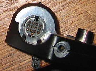
Roland 13 Pin Din GKpickup to GRsynth
DIN-13 PINOUT

Pin 1 = String 1
Pin 2 = String 2
Pin 3 = String 3
Pin 4 = String 4
Pin 5 = String 5
Pin 6 = String 6
Pin 7 = mono guitar signal
Pin 8 = synth volume
Pin 9 = no connection
Pin 10 = switch 1
Pin 11 = switch 2
Pin 12 = +7VDC power
Pin 13 = -7VDC power
Sleeve = Ground
FRONT VIEW OF JACK (FEMALE CONECTOR)

4 3 2 1

8 7 6 5

12 11 10 9

13

The shell (sleeve) connection is Ground.
The original Roland guitar synths used an extremely proprietary connector for the cable.


And here's the pinout and colour codes for the C24-D cable:
| C24-D pin | Signal | Wire colour | GK-2a pin | ||
|---|---|---|---|---|---|
| 1 | +15V | brown & stripe | 12 (+7V) | ||
| 2 | -15V | brown | 13 (-7V) | ||
| 3 | GND | orange | |||
| 4 | GND | red & stripe | |||
| 5 | GND | red | |||
| 6 | GND | yellow & stripe | |||
| 7 | n.c. | yellow | 9 | ||
| 8 | M. VOL | orange & stripe | |||
| 9 | S. VOL | dark green & stripe | 8 | ||
| 10 | G. VOL | dark green | |||
| 11 | CV1 | dark blue & stripe | |||
| 12 | CV2 | dark blue | |||
| 13 | CV3 | gray | |||
| 14 | CV4 | purple & stripe | |||
| 15 | SW1 | purple | 10 | ||
| 16 | SW2 | pink & stripe | 11 | ||
| 17 | n.u. (grounded) | pink | |||
| 18 | G. SIG | gray & stripe | 7 | ||
| 19 | #1 | light green | 1 | ||
| 20 | #2 | black & stripe | 2 | ||
| 21 | #3 | black | 3 | ||
| 22 | #4 | light blue & stripe | 4 | ||
| 23 | #5 | light blue | 5 | ||
| 24 | #6 | light green & stripe | |||
=============================================== --->
MIDI
Interface Bus; [Musical Instrument Digital Interface]: defines the
electrical and physical interface over a 5-pin
MIDI also defines the protocol used over the interface.
The MIDI interface uses three different pinouts which are all defined on a 5-pin
DIN connector; MIDI In, MIDI Out, and MIDI Thru.
5 pin male connector

| Pin No. | IN Signal Name | THRU Signal Name | Out Signal Name |
|---|---|---|---|
| 1 | No Connect | No Connect | No Connect |
| 2 | No Connect | Shield | Shield |
| 3 | No Connect | No Connect | No Connect |
| 4 | IN+ | +5v | +5v |
| 5 | IN- | IN | IN |